The official CASEIS Cruise Blog is located here: http://www.ipgp.fr/caseis This official blog is written by my shift-mate Lola Johannes.
We are refreshed by the blowing wind as we follow it back to port to exchange some crew members (including yours truly), to get some replacement core curation materials, and have one night out on the town before returning to sea for leg 2 of CASEIS.
Leg 1 Comes to an End on 2016/06/20; Leg 2 begins 2016/06/21
June 19, 2016
- We are preparing to core our final cores here on the bridge. From the left are Jean Marie, Dr. Feuillet, Theo (the engineer controlling the ship at the bridge), and Dr. Leclerc. We have an upcoming paper plane competition and Nathalie has two prototypes in her hands. Awards will be based upon overall points, longest flight, best design, and most acrobatics.
- Dr. Christian Beck presented material on sedimentation in a marine setting. He discussed the various inputs, different depositional processes, and the deposits that we have observed in the cores during leg 1 of this cruise.
- What was almost our last piston core for leg 1 returned to the ship in the shape of a pretzel. The core did not penetrate much into the seafloor, so bended to absorb the force of the weight stand.
- Here the 8P-12A shift cuts this core CAS16-28PC. From left to right, Olivia, Artur, and Eva. The sediment at the top and base of the core was 99% organic matter (partially decomposed woody debris. I strongly advocated for a box core at this site. We did not know what was in the PC core (only 1 meter long) and a box core could be used to establish (1) depositional rates here and (2) whether recent seismicity was recorded at this location.
- Here Artur and Eva clean and label this core.
- Dr. Feuillet and the captain discuss her stereo microscopic observations of the organic woody debris.
- The location of this and the box core CAS16-29BC are at the middle of the red line in the map below. Color represents depth and the color scale on the right shows red = shallow and blue = deep. The blue areas are in the trench. The green/orange areas are (1) on the left, the accretionary prism and (2) on the right, the Barracuda ridge (associated to a fracture zone and likely controls segmentation of the subduction zone).
- Here is a view of the seafloor surface as collected in the box core CAS16-29PC. The surface is an oxidized red-brown clay.
- Here Marie and Dr. Ratzov watch Dr. Beck insert one of the sub-sampling cores into the box core. We drilled holes into the pipe and are using a threaded rod as a handle to insert the pipe.
- This is an exposure of 29BC. Quentin D. is pleased that this core contains interesting stratigraphy. The base is a grey-green clay. As we remove sediment so that we can collect the sub-sample cores, we learn more about the stratigraphy.
- This is a close up view of the core after we removed some sediment. This is a great way to see the stratigraphy. There are reddish brown layers and these layers appear to have a high organic content. The CT data from these cores will be very interesting. We do not see any turbidites here, but muddy turbidites are difficult to see with the naked eye. There are some parts of the stratigraphy that appear to not be laminated like the reddish brown layers.
- We moved the ship to a nearby location to take another piston core. Here the engineers change the core position from horizontal to vertical.
- Here Theo and Martin discuss the ship’s operations as we conduct seismic surveys for the remaining of leg 1.
- Here is a compilation map showing the location of all our cores locations cored on leg 1 of CASEIS.
The official CASEIS Cruise Blog is located here: http://www.ipgp.fr/caseis This official blog is written by my shift-mate Lola Johannes.
Designs
June 17, 2016
- I have prepared a t-shirt and logo design as part of a competition. I first was told that there was a t-shirt design competition, so I spent an hour or so putting together a design. Later I learned that the competition was for a logo, not a t-shirt. I just reconfigured the shirt design into a smaller logo design. Stay tuned for the results from the competition.
T-Shirt Design
Logo Design
The official CASEIS Cruise Blog is located here: http://www.ipgp.fr/caseis This official blog is written by my shift-mate Lola Johannes.
Site Selection with Sunsets and Sunrises
June 15, 2016
- We are collecting both shallow sub-bottom CHIRP seismic reflection data as well as deeper streamer seismic reflection data. The CHIRP data (the lower image below) tells us what sediments we might be able to core, how deep we could core, and the relative material properties of those sediments. If the sediments are too sandy or stiff, we cannot core as deeply into those sediments. Otherwise, the core will either (1) hit the stiff sediments before being fully embedded into them, causing the core barrel to bend or (2) get stuck in the sediments causing a large tension on the cable when being pulled out. So far on this cruise, we have had a minor core barrel bend and also have had a core stuck. The deeper seismic data help us interpret the relative age of the sediments observed in the CHIRP data. If the potential coring location has been a depocenter for a long time (a place where sediments pile up, like a sedimentary basin), then we will see these sediments in the deeper seismic data. The upper image below is the streamer seismic data in the same general region as the CHIRP data. We see that this sedimentary basin is a long lived depocenter (at least into the Pleistocene (up to 2.56 Ma), perhaps even longer).

- There are three wires trailing the ship for this streamer seismic survey (they are the “Streamers”). This photo shows the center streamer as a white cable leaving the stern of the ship. On the starboard and port sides, there are two more streamers. One may observe the white circles of bubbles formed when a sound waves are projected to the seafloor.
- Here Dr. Beck is using the acquired multibeam sonar bathymetry data to help us locate a good coring site. The blue represents deeper water and yellow represents shallower water.
- This is another beautiful sunset to a very successful work day.
- Here are, from left to right, Dr. Feuillet, Chloe, and Lola.
- Here are Quentin #1 and Olivia.
June 16, 2016
- And then another beautiful sunrise to begin the next day. The lucky part about our shift is that on one shift we see the sunrise (4-8 AM) and on the other shift, we see the sunset (4-8 PM).
- Here are, from left to right, Quentin #1, Gaelle, Marie, and Quentin #2.
The official CASEIS Cruise Blog is located here: http://www.ipgp.fr/caseis This official blog is written by my shift-mate Lola Johannes.
Box Cores, mud pies, and BBQ.
- Here is a site map for the cores that we have collected so far. This is similar to maps that I have previously posted. The dots in blue show the locations of our actual core sites. We recently collected a 20.02 m piston core CAS16-21PC in an isolated basin east of the main slope, a basin formed by a backthrust fault in the western accretionary prism. We also collected a box core (CAS16-22BC) in this same location. Based upon correlations between PCs and BCs, it is good that we are collecting these BCs as there is from 0-30 cm missing sediment at the tops of our PCs. Also, BCs are better for sampling for 210Pb since the uppermost sediment in PCs, even if it is completely there, is disturbed when we curate the cores on the deck.
June 14, 2016
- Here Chloe anxiously awaits the arrival of 22BC. The ship’s engineers are getting ready to bring it on board.
- Here the engineers carefully lower the BC onto the deck.
- Here the engineers unbolt the part of the corer that contains the sediment from the part of the corer that has the rest of the mechanisms for coring. This is similar to the piston corer, where there is the core barrel and the rest of the mechanisms.
- Next we drain the water from the top of the core by drinking the sea water. Not really, we just use this tubing to siphon the water. Quentin D. is on the left and Charles Deschamps, from another shift, helps us do this because this is our first BC and he has done this for 4 BCs.
- We remove some sediment stuck to the outside of the BC, captured by the trap door used to keep the sediment in the core. Dr. Beck shows us that there are abundant forams in this sediment. Look for the small white grains exposed in the sediment. Those are the forams. Whomever gets to pick the forams for radiocarbon age control will be lucky since they are so large (this requires fewer numbers of forams than in an oceanographic setting that has smaller sized forams, like the northeast Pacific).
- Then we measure the thickness of the sediment so that we can cut the sub-sampling cores to the correct length.
- Here Quentin holds the sub-sampling core as Dr. Beck cuts it with his meat cutting saw.
- Here Chloe, Gaelle, Lola, and Marie show us that they have cleaned and labeled the cores. We will take 3 sub-samples.
- Here Chloe inserts the core into the sediment.
- Here Quentin D. measures the sediment inside and outside of the core to determine how much compaction might have occurred inside of the core.
- We can see that there are abundant forams on the surface of the sediment, along with some small pieces of shell (the larger white pieces).
- Next we remove some bolts to allow us to lift up the side of the BC. This reveals the sediment stratigraphy. The sediment in this core does not appear to have any sandy turbidites in the surface. There may be muddy turbidites, but we will need to wait until we can CT scan the sub-sample cores.
- Then we dig out the sediment surrounding the sub-sample cores so that we can place caps on them.
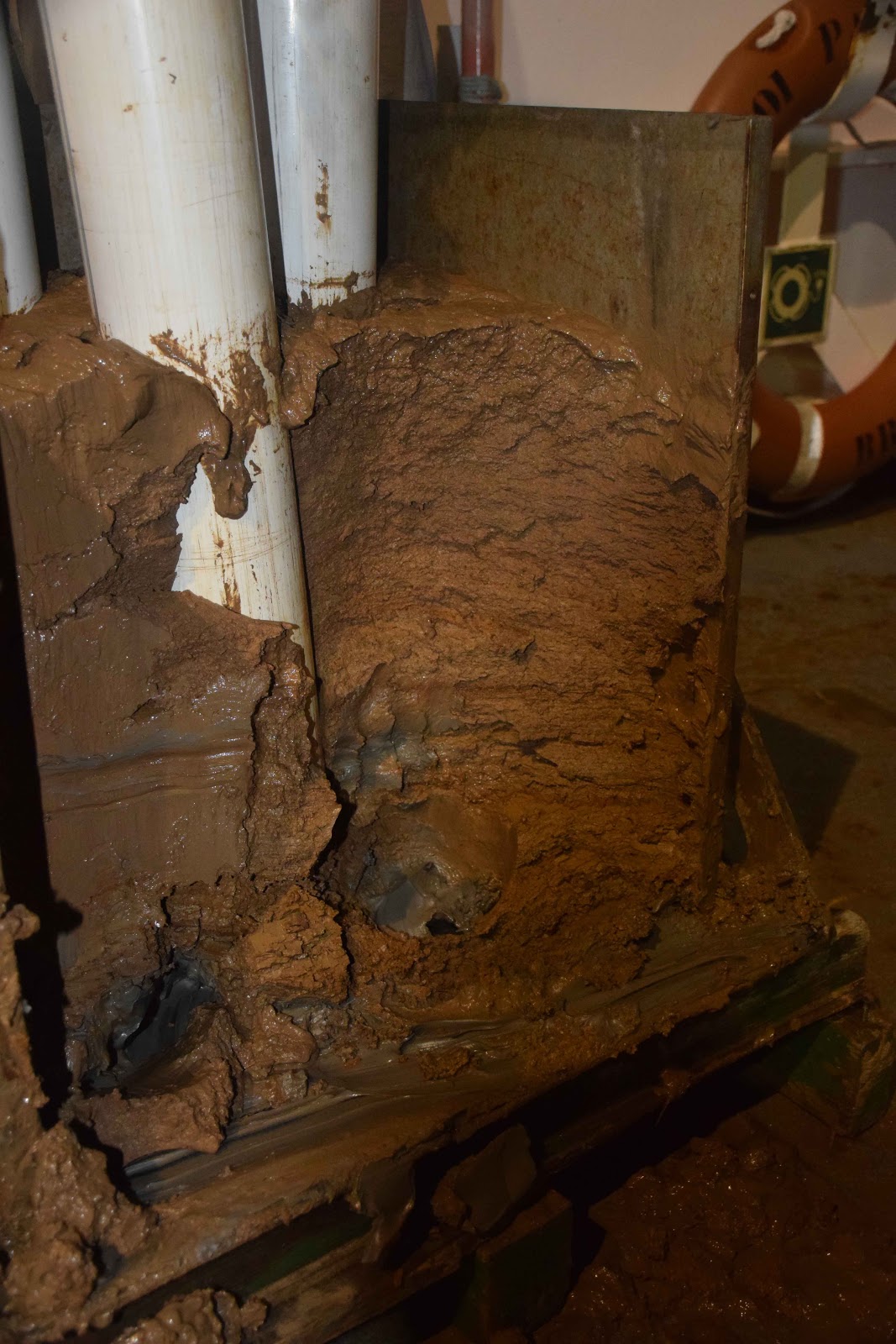
- This process allows for a well-deserved stress reliever, the mud fight. People got to paint each other with mud and this was lots of fun. Here is Marie modeling her mud markings.
- Here my shift mates continue to play with the mud as they clean out the BC. There is nothing better than a mud fight as it helps people to remember to have fun. I watch from the sidelines to ensure that I can prevent mud from getting into my camera. Heheh.
- This is the sunset from the end of this day.
- Dr. Feuillet and the second chief mate Martin work closely together to navigate around a small target area in the subduction zone trench. We found some promising CHIRP seismic data but the trench is filled with hummocky topography and the target sedimentary layers are in small regions between the hummocks.
- This is a panorama from the bridge.
- Patrice Woerther gave a presentation today about how he and his colleagues have designed the coring system used on the ship. This system uses pressure transducers and accelerometers to evaluate how the piston coring system performs while coring. These data allow them to configure the coring system to collect sediment in the core that is not deformed.
The official CASEIS Cruise Blog is located here: http://www.ipgp.fr/caseis This official blog is written by my shift-mate Lola Johannes.
We have challenges and overcome them...
June 10, 2016
Here Dr. Beck discusses the sedimentary structures in this core to Dr. Feuillet, Gaelle, and Lola.
This shows a ball and pillow structure that Dr. Beck was discussing in the above photo. The top of the core is to the left. The sediment on the left is a sand at the base of a turbidite. The brown sediment below this sand is hemipelagic sediment (background sedimentation between turbidites and tephras). Below the hemipelagite is another turbidite. As the overlying turbidite was deposited, it caused a heavy load in the underlying sediment, causing some of the sediment to push up and some to push down. This is the cause of this ball and pillow structure (the wavy contact between the sand and the hemipelagite between 38 and 44 cm).
We are making good time on our cruise, as the N/O Pourquoi Pas cuts through the sea.
June 11, 2016
I presented my research offshore of Sumatra today. This talk was well attended by both science crew and the ship’s crew. The main purpose was to help the science crew learn about turbidite Paleoseismology. I discussed one of the key tools used to discriminate from various different landslide triggering mechanisms.
The core cutting saw malfunctioned today. We are equipped to repair our instruments as there is not a hardware store around the street corner or in the local neighborhood. Tony, part of the coring engineer crew, repairs the core cutting saw.
Here Dr. Beck and Lola describe the stratigraphy found in core CAS16-16PC.
This is a plot of the wire tension. The vertical axis is tension in tons (1-14 tons). Time is from left to right. As the core is being lowered, the tension fluctuates between 4 and 5 tons due to ship heave (ocean swell) and the elastic nature of the cable. When the core drops into the sediment, the tension rapidly drops to about 1 ton (the weight of the cable, etc.). Then the winch is operated to pull the core out of the mud. This is represented by an increase in tension, up to about 12 tons. At this point, the tension drops to the ambient weight of the sediment core, the weight stand, and the cable. Note how the weight is slightly more than it was before the core went into the sediment. This difference is the weight of the sediment in the core.
Here Chloe give us a thumbs up because we see that there is sediment covering the outside of the core pipe (telling us that the core was embedded in sediment.
Dr. Beck looks at the sediment to see what type of sediment that the core sampled. We found that there were foraminifera in this sediment, so this core will be useful for radiocarbon age control.
June 12, 2016
Here the ship’s crew prepares another piston core. Note that they are wearing all the appropriate safety gear (steel toe boots, helmets, and life vests). The large rectangular shaped device on the top of the core is the weight stand. The red, white, and orange rectangular shaped objects are weights. We can change the amount of weight in the weight stand depending upon how deep we want to core. The deeper that we want to core, the more weights we use.